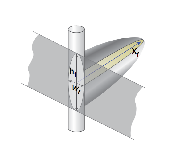
Half of the total length
X_f = 0.5 \cdot L_f of the hydraulically induced vertical plane fracture (see Fig. 1).
|
| Fig. 1 – Hydraulic fracture schematic showing fracture half-length (Xf), fracture height (hf) and fracture width (wf). |
For the fractured vertical well the geometrical skin-factor S_G is related to Fracture half-length X_f as:
| (1) | S_G= -\ln \left(\frac{X_f}{r_w} \right) + \frac{1.65 -0.328 \, u + 0.116 \, u^2}{1+0.18 \, u + 0.064 \, u^2 +0.05 \, u^3} |
where
u = \ln F_{CD} | |
F_{CD} | dimensionless hydraulic fracture conductivity |
In case of high dimensionless hydraulic fracture conductivity (corresponding to infinite conductivity fracture case) the skin-factor model can be simplified:
| (2) | S_G = -\ln \left(\frac{X_f}{2\, r_w} \right) |
See Also
Petroleum Industry / Upstream / Well / Well-Reservoir Contact (WRC) / Hydraulic Fracture