Collective term for Cased-Hole Logging operations in producing wells with a purpose to assess Borehole Flow Profile (BFP) and/or Reservoir Flow Profiling (RFP):

Borehole Flow Profile (BFP)Reservoir Flow Profiling (RFP)
Borehole Production ProfileBorehole Injection ProfileReservoir Production ProfileReservoir Injection Profile


PLT is essential part of the production and recovery monitoring and helps understand fluid communication at Well-Reservoir Contact.

For PLT in injection well see ILT, although it is often called PLT anyway.

The survey is performed with a multi-sensor downhole PLT Logging Tool and interpreted with PLT-BFP Model or PLT-RFP Model.

Objectives


Picking up the fluid inflow intervals and phase characterization

Estimating flowrate of each phase component across each inflow interval
Check up for cross-flows in shut-in conditions between formation units with different formation pressure

Picking up the zones of the first barrier (tubing and/or casing) integrity failure


Conclusions

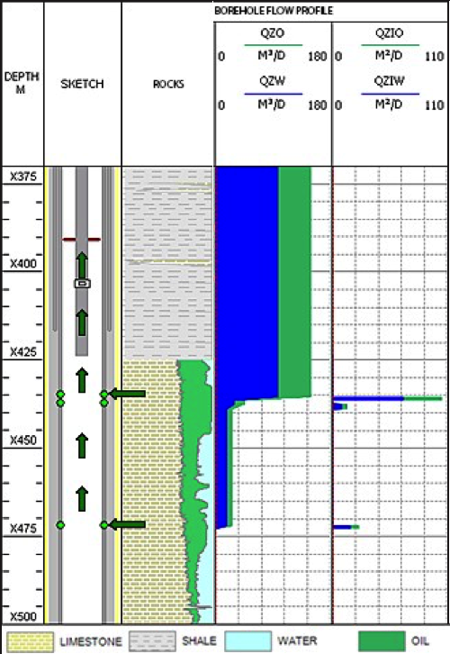
Both perforations are producing oil and water with upper interval producing more than lower.

The lower inflow zone is mostly producing water.


Fig.1. PLT in oil producer with oil and water production.

See ILT for example in injecting well.


See Also


Petroleum Industry / Upstream /  Data Acquisition / Well & Reservoir Surveillance / Well logging / Cased-Hole Logging

Well & Log Analysis ][ Borehole Flow Profile (BFP) ]Reservoir Flow Profiling (RFP) ]Temperature Logging ][ Noise Logging ]

PLT – Donwnhole Tools ] [ PLT – Logging Procedure ] [ PLT – Interpretation ] [ PLT – Samples ]

Injection Logging (ILT) ]


References


Richard Bateman, Cased Hole Log Analysis and Reservoir Performance Monitoring, 2015

http://petrowiki.org/Production_logging


Parijat Mukerji, Production Logging Principles


Lulu Liao, INTERPRETATION OF ARRAY PRODUCTION LOGGING MEASUREMENTS IN HORIZONTAL WELLS FOR FLOW PROFILE – 2013


SPWLA-56-Pitfalls-of-running-conventional-production-logging-in-horizontal


PRODUCTION LOGGING TEST IN HORIZONTAL WELLS


Kappa_PLT_Report.pdf

1. PVT model


 1.1. Understanding of Black-Oil fluid model


 1.2. Formation Volume Factor: Bw, Bo, Bg (including separator corrections)


 1.3. Phase viscosities: mu_w, mu_o, mu_g


2. Zonal Analysis


 2.1. Location of inflow zones


 2.2. Location of calibration zones (based on flow stability)


 2.3. Location of calculation zones (based on flow stability)


 2.4. Locate cross-flow zones (based on temperature and raw FBS data)


3. Total Flowrate


        3.1. Flowrate Sensors


  3.1.1 Mechanical spinner (FBS, ILS, CFS) 


  3.1.2. Anemometer (HEX)


  3.1.3. Ultrasonic (UZI)


  3.1.4. XY Caliper (XYC)


 3.2. Flow velocity


  3.2.2. Calibration cross-plot (threshold, slope, non-linearity and ceiling at high V)


  3.2.3. Flow velocity calculation (cable speed correction)


 3.3. Flowrate Profile 


  3.3.1. Cross-sectional flow profile (from parabolic for laminar flow to flat for turbulent flow) and how to set the correction coefficient


  3.3.2. Building Q and QZI profiles


  3.3.3. Additional Analysis and QC 


   3.3.3.1. Against FBS/ILS/HEX stations 


   3.3.3.2. Against the latest production tests and reallocated production history


   3.3.3.3. Against pipeline pressure drop (flowing vs shut-in)


   3.3.3.4. Understanding of flowrate accuracy


4. Phase Hold-ups


 4.1. Phase Sensors 


  4.1.1. Understanding RECAP (calibration and dynamic water hold-up)


  4.1.2. Understanding CAP (calibration for gas/oil/water and dynamic gas hold-up and non-linearity at high water-cuts)


  4.1.3. Understanding HEX (calibration and fluid indication)


  4.1.4. Understanding DENSP (calibration and fluid indication)


 4.2. Phase slippage (what correlations to use in vertical, slanted, horizontal) and its impact on saturations


 4.3. Recalculating the flowrates to surface conditions


5. Multifinger PLT 


 5.1. Understanding of muliti-phase horizontal flow 


 5.2. Understanding of linear and circumferential sensor arrays (including the angle correction)


 5.3. Building the integral QZI flow profile from array-data


6. Regulations


 6.1. Input Data


 6.2. Logging Procedure


 6.3. Output Data and Final Report