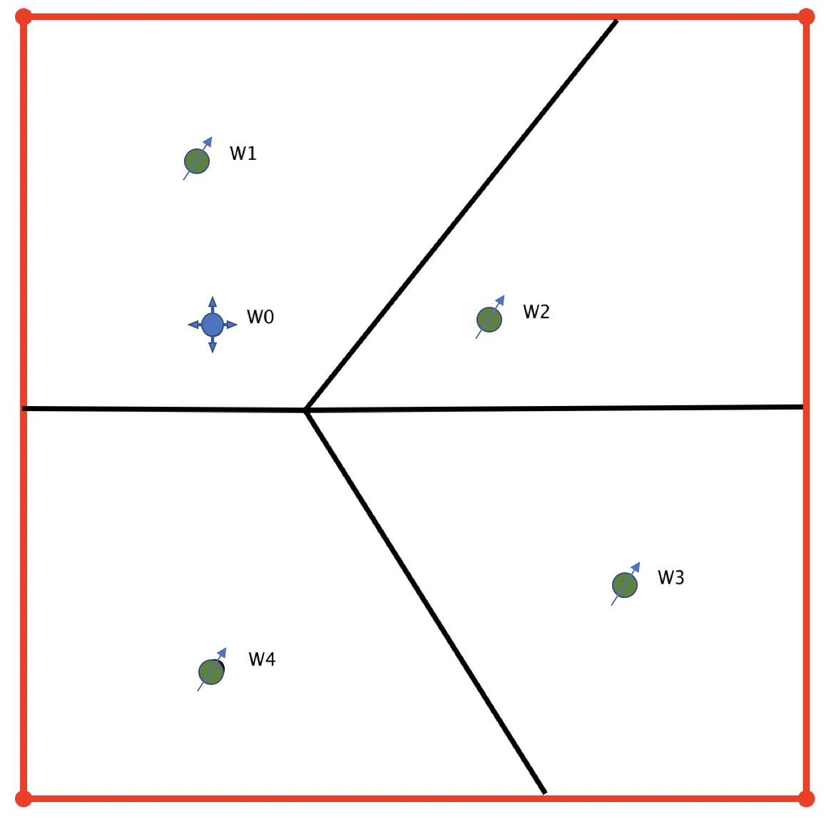
Consider a well-reservoir system (Fig. 1) consisting of:
- producing well W1 with total sandface flowrate
q_1(t)>0 and BHP
p_1(t)>0, draining the reservoir volume
V_{\phi, 1}
water injecting well W0 with total sandface flowrate q_0(t) <0, supporting pressure in reservoir volume V_{\phi, 0}
The injection drainage volume
V_{\phi, 0} includes the drainage volume
V_{\phi, 1} of producer W1 and may be equal to it
V_{\phi, 0} = V_{\phi, 1} or may be bigger
V_{\phi, 0} > V_{\phi, 1} in case injector W0 supports other producers {W1 .. WN}:
V_{\phi, 0} = \sum_{k=1}^N V_{\phi, k}.
|
| Fig. 1. Location map of injector-producer pairing with 4 producers {W1, W2, W3, W4} and one injector W0. |
Case #1 – Constant flowrate production: q_1 = \rm const >0
The bottom-hole pressure response \delta p_1 in producer W1 to the flowrate variation \delta q_0 in injector W0:
| (1) | \delta p_1 = - p_{u,\rm 21}(t) \cdot \delta q_2 |
where
t | time since the water injection rate has changed by the \delta q_2 value. |
p_{u,\rm 01}(t) | cross-well pressure transient response in producer W1 to the unit-rate production in injector W0 |
|---|
Case #2 – Constant BHP: p_1 = \rm const
Assume that the flowrate in producer W1 is being automatically adjusted by \delta q_1(t) to compensate the bottom-hole pressure variation \delta p_1(t) in response to the total sandface flowrate variation \delta q_2 in injector W0 so that bottom-hole pressure in producer W1 stays constant at all times \delta p_1(t) = \delta p_1 = \rm const. In petroleum practice this happens when the formation is capable to deliver more fluid than the current lift settings in producer so that the bottom-hole pressure in producer is constantly kept at minimum value defined by the lift design..
In this case, flowrate response \delta q_1 in producer W1 to the flowrate variation \delta q_0 in injector W0 is going to be:
| (4) | \delta q_1(t) = - \frac{\dot p_{u,\rm 01}(t)}{\dot p_{u,\rm 11}(t)} \cdot \delta q_0 |
where
t | time since injector's W0 rate has changed by \delta q_0. |
\dot p_{u,\rm 01}(t) | time derivative of cross-well pressure transient response (CTR) in producer W1 to the unit-rate production in injector W0 |
|---|---|
\dot p_{u,\rm 11}(t) | time derivative of drawdown pressure transient response (DTR) in producer W1 to the unit-rate production in the same well |
For the finite-volume drain V_{\phi,1} \leq V_{\phi,0} < \infty the flowrate response factor \delta q_1 / \delta q_0 is getting stabilised over time as:
| (11) | \delta q_1 / \delta q_0 = - f_{01} = - \frac{V_{\phi, 1}}{ V_{\phi, 0}} = \rm const |
The response delay in time still exists but in usual time-scales of production analysis it becomes negligible and one can consider
(11) as constant in time.
In case injector W0 supports only one producer W1 , then both wells drain the same volume and
V_{\phi, 0} = V_{\phi, 1} so that
(11) leads to:
| (14) | \delta q_1 = -\delta q_0 |
which means that producer W1 with constant BHP and finite-reservoir volume will eventually vary its rate at the same volume as injector W0.
In case injector W0 supports many producers {W1 .. WN} then all injection shares towards producers are going to sum up to a unit value:
| (15) | \sum_{k=1}^N f_{0k} = 1 |
unless there is thief injection outside the drain area of all producers and in this case:
| (16) | \sum_{k=1}^N f_{0k} < 1 |
If pressure in producer W1 is supported by several injectors
N_{\rm inj} > 1 then over a long period of time one can assume:
| (17) | \delta q_1 =\sum_k f_{k1} \delta q_k |
with constant coefficients f_{1k}, \ {k=\{1..N_{\rm inj} \} }, which makes one of the key assumptions in Capacitance Resistance Model (CRM).
See also
[ DTR ] [ CTR ] [ Capacitance Resistance Model (CRM) ]