|
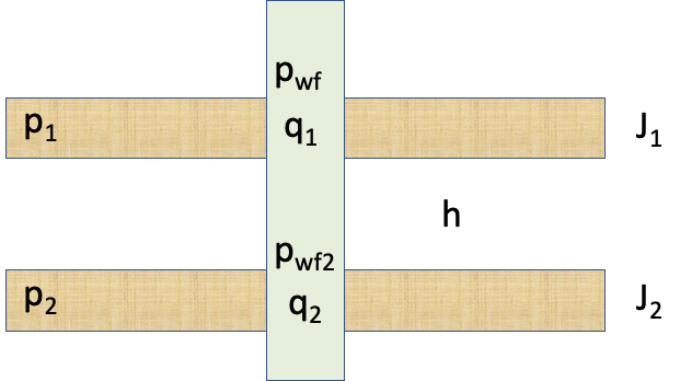
| Fig. 1. Multi-layer well schematic |
|
|
| ||||||
| ||||||||
where
q | total subsurface flowrate of the well |
|---|---|
J | total well productivity Index |
p_e | apparent formation pressure of dual-layer formation |
p_{wf} = p_{wf, k_{ref}} | bottom-hole pressure at the top of the reference layer k_{reff} |
p_{wf,k} = p_{wf} +\delta p_k | bottom-hole pressure at the top of the k-th layer |
\delta p_k | wellbore pressure loss between k-th layer and reference layer k_{reff} |
q_k | total subsurface flowrate of the k-th layer |
p_k | formation pressure of the k-th layer |
J_k | productivity Index of the k-th layer |
The above equations are valid for both producers q>0 and injectors q<0.
In many practical cases:
| (5) | \delta p_k = \rho \, g \, h_k |
where
\rho | wellbore fuid density |
|---|---|
g | gravity constant |
h_k = TVDSS_k - TVDSS_{k_{ref}} | true vertical height between k-th layer and reference layer k_{reff} |
See Also
Petroleum Industry / Upstream / Production / Subsurface Production / Subsurface E&P Disciplines / Field Study & Modelling / Production Analysis / Productivity Diagnostics